Motorcycle Regulator Rectifier Wiring Diagram
A magnet on a shaft spins within the stator, creating alternating current (ac). 125cc xrm 125 cdi wiring diagram haisayacarlmilia adding a battery to my startv bike moped army 2 3 and 4 wire rectifiers understanding motorcycle voltage regulator homemade circuit projects g rectifier regulater atv gy6 50 150cc scooter wires boat at affordable s free shipping real reviews with photos joom this.

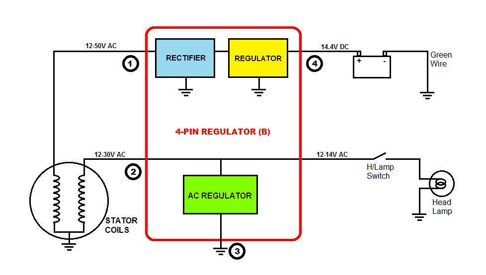
12v 3 Phase Motorcycle Regulator/rectifier Circuit Wiring Diagram
Simply plug the connector onto the 5 pins row and make sure that the pin assignments and wire assignments are matched correctly.
Motorcycle regulator rectifier wiring diagram. Occasionally, the cables will cross. The proposed 3 phase motorcycle voltage regulator circuit for motorcycle may be witnessed in the diagram below. Universal dc unwired regulator/rectifier by baja designs®.
The 3 phase output from the alternator is sequentially applied across three power transistors which basically act like shunting devices for the alternator current. In this system, both the ends of the winding go to the rectifier section which converts ac to dc voltage and then the regulator section regulates to 14.4v as discussed above. Furthermore, wiring diagram provides you with the time frame by which the projects are for being finished.
(see diagram below) regulator rectifiers you must use resisted spark plugs as circuitry is sensitive. It sounds like you are searching for a regulator/rectifier? 3 phase 6 wire regulator rectifier wiring diagram.
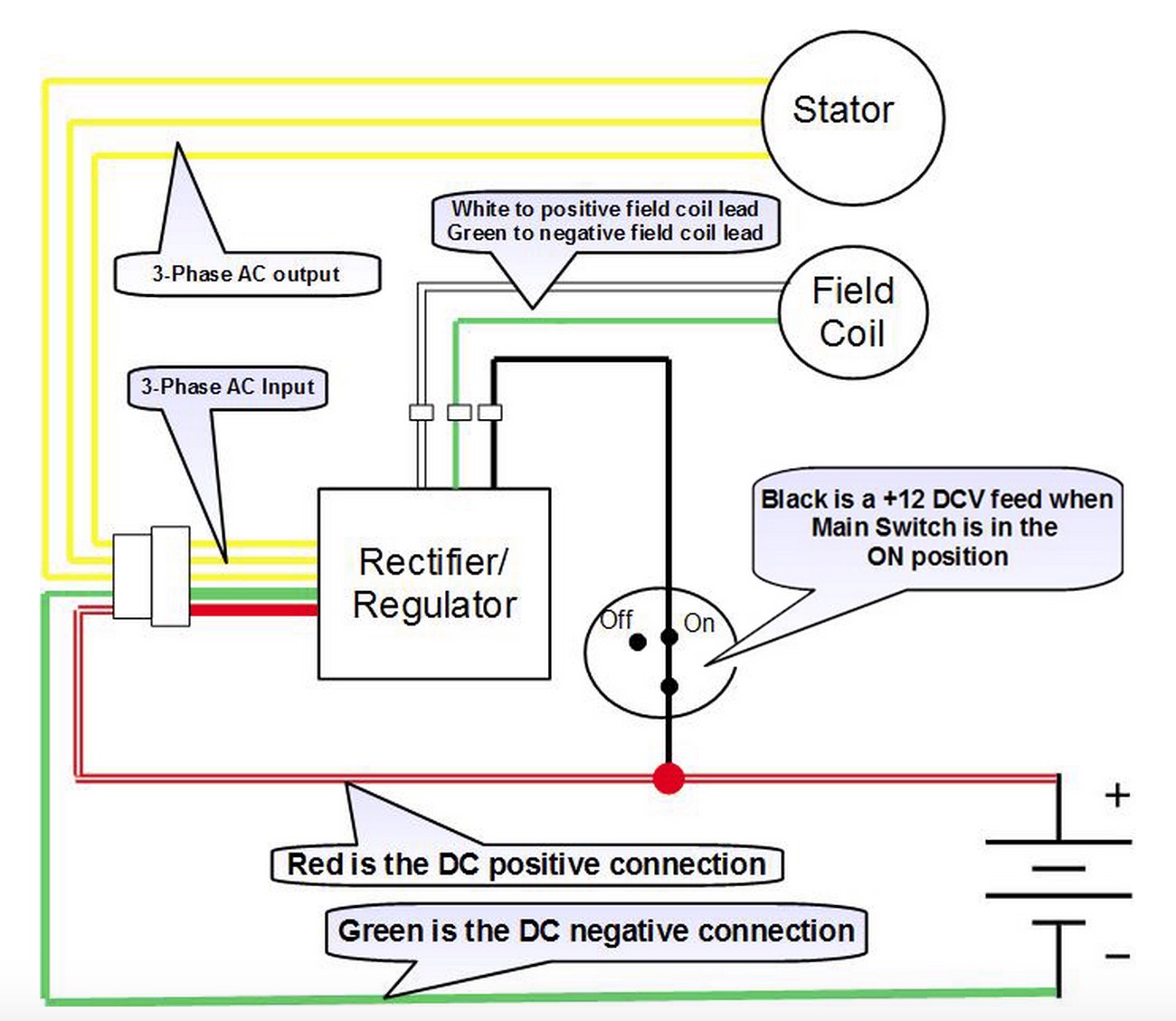
You will be capable to understand precisely if the assignments should be accomplished, which makes it easier for you personally to. However this diagram is a simplified version of this arrangement. 2 from the alternator 1 fromto the battery positive 1 to ground negative and another also to the battery.
Here are a number of highest rated motorcycle regulator rectifier wiring diagram pictures upon internet. Marvellous motorcycle regulator rectifier wiring diagram ideas size. Motorcycle regulator rectifier wiring diagram.
2 phase 5 wire motorcycle regulator rectifier wiring diagram pdf. Lamberts bikes motorcycle part wiring diagrams. This type may be found on some motorcycles.
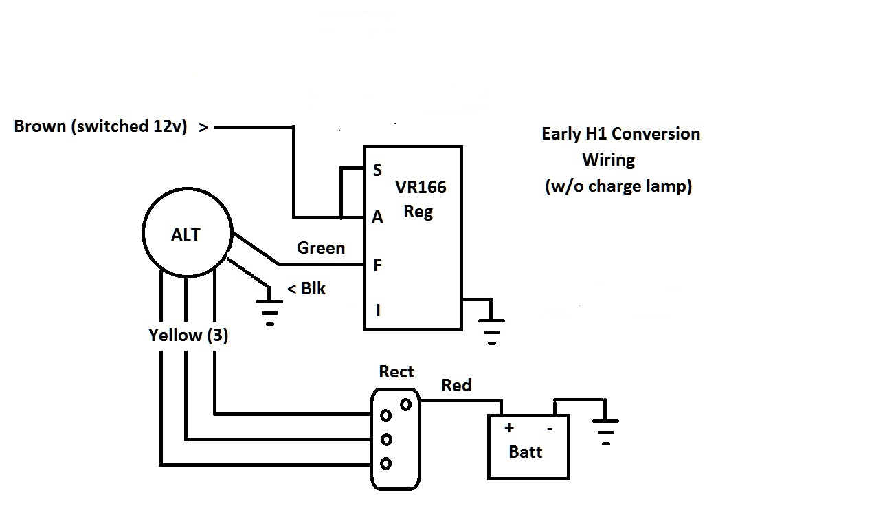
Provided below is an online pdf document for lamberts bikes 3 phase 6 wire regulator rectifier wiring diagram. 15 amp regulator rectifier for kohler k magnum mand and other. For example, on a 1981 kawasaki kz440, there are 5 wires going to the oe part:
Injunction of 2 wires is usually indicated by black dot at the junction of two lines. The schematic is rather easy to understand. A few notes i pulled this schematic out of an older scooter repair manual.
Trail tech stators have yellow lighting leads. There’ll be principal lines which are represented by l1, l2, l3, and so on. M 3 2 2 2 phase 5 wire.
Wiring diagram for voltage regulator. For example on a 1981 kawasaki kz440 there are 5 wires going to the oe part. Understanding motorcycle voltage regulator wiring homemade circuit projects tbolt usa tech database llc rectifier tester new to indiana 650 6 wires stock can i use 5 wire ducati ms the ultimate forum magneto for 2 4 stroke swap pocketbike yamaha xv250 1995 2005 klimmodontologia com br building a electronics forums china pins 12 150 250cc spare.
Its submitted by running in the best field. However, it doesn’t mean link between the cables. Regulator rectifier diagram here you are at our site this is images about regulator rectifier diagram posted by maria nieto in wiring category on may 08 2019.
This is the ultimate guide to the humble motorcycle regulator rectifier. Many rick’s motorsport electrics rectifier/regulators eliminate what is commonly referred to as a “signal wire” on original equipment (oe) pieces. We ve even included standard wire colours where appropriate.
(see diagram below) regulator rectifiers you must use resisted spark plugs as circuitry is sensitive. This version of the baja designs voltage regulator/rectifier comes without connectors or fuse block and has generic length wiring (12). It is not recommended for use with bike.
Connect to lighting leads from stator. 12v three phase regulator rectifier fitting instructions. As stated earlier, the lines at a rectifier regulator wiring diagram signifies wires.
We identified it from trustworthy source.

12v 3 Phase Motorcycle Regulator/rectifier Circuit Wiring Diagram
6 Pin Regulator Rectifier Wiring Diagram How To Test Your Motorcycle Charging System A


5 Pin Regulator Rectifier Wiring Diagram / Regulator Rectifier As Honda Xl600 Trx350 Trx400 5

Understanding Motorcycle Voltage Regulator Wiring

BATTERY SOLUTIONS Modification Rectifiers Regulator Motorcycle

16+ Motorcycle Rectifier Circuit Diagram Motorcycle wiring, Voltage regulator, Electrical
Aftermarket Honda Regulator Rectifier OEM Style Honda Replacement Part

12v 3 Phase Motorcycle Regulator/rectifier Circuit Wiring Diagram
Voltage Regulator / rectifier units


Understanding Motorcycle Voltage Regulator Wiring
650 Rider > > xs650 > > Motorcycle Systems > > Electrical > > REGULATOR RECTIFIER HELP


Image result for 12v rectifier regulator wiring diagram Regulators, Power source, Wire
12v 3 Phase Motorcycle Regulator/rectifier Circuit Wiring Diagram

Motorcycle Rectifier Circuit Diagram Motorcycle You
12v Rectifier Regulator Wiring Diagram Wiring Diagram
Motorcycle Regulator Rectifier Wiring Diagram Collection Wiring Diagram Sample

BATTERY SOLUTIONS Modification Rectifiers Regulator Motorcycle
How To Test A Regulator/rectifier Youtube Rectifier Regulator Wiring Diagram Cadician's Blog
How to Test Your Motorcycle Charging System — A Comprehensive Guide Motofomo