Kübler Encoder Wiring Diagram

Honda Xr200 Wiring Diagram, Skygo150 Voltage Regulator for XR200/Actual Wiring/Honda XR200 Modified/Supermoto/DIY Garage PH, 10.03 MB, 07:18, 10,383, D I Y Garage PH, 2021-01-23T08:48:03.000000Z, 19, Iam looking for a 1982 honda xr200 wiring diagram, www.justanswer.com, 904 x 703, jpeg, wiring diagram 1982 honda xr200 xt200 yamaha manual iam motorcycle looking 1981 mechanic bikee wire, 20, honda-xr200-wiring-diagram, Anime Arts
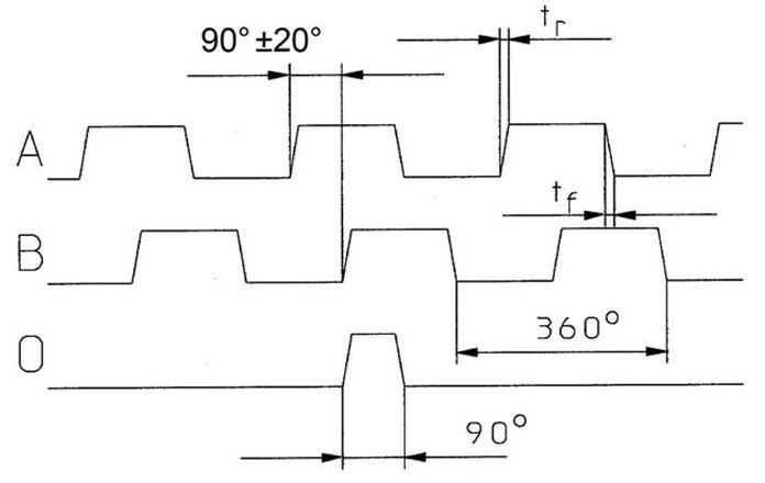
Kübler by turck incremental encoders 2. 5 (t8. 5820) incremental hollow shaft encoder part number key 2. 5 (t8. 5800) incremental shaft encoder part number key 1 = clamping flange ø58 mm 2 = servo flange ø58 z = 2. 5 square flange (63. 5 mm) w/shaft seal flange 1 = ø6 mm x 10 mm 2 = ø10 mm x 20 mm shaft t8. Incremental encoders are available in two basic output types, single channel and quadrature. A single channel encoder, often called a tachometer, is normally used in systems that rotate in one direction only, and require simple position and velocity information. Quadrature encoders have dual channels (a and b), phased 90 electrical degrees apart.
In order to observe rotary encoder pulse output intuitively. The standard totalizers bk 14 (manually resettable) have a robust design despite their small size. They are used in harsh industrial environments. Encoders incremental and absolute shaft and hollow shaft variants size ranging from miniature ø 24 mm to maxi ø 100 mm. Kubler encoder wiring diagram source: Cdn2. hubspot. net read cabling diagrams from negative to positive in addition to redraw the routine being a straight collection. All circuits are usually the same : Voltage, ground, solitary component, and switches. It has proved its value in many industries as a robust and precise sensor technology.
Kubler (Germany) Kueber Incr. encoder A 25 Pulse 8.5810.1215.0025 10-30VDC | Output(Encoders

Kuebler - Wire Encoders B80 SERIE D8.XB1 | OEM Automatic Ltd

Kuebler - Wire Encoders B80 SERIE D8.XB1 | OEM Automatic Ltd

Frequently Asked Questions For Kubler Products and Technologies | Valin

Kuebler - Wire Encoders B80 SERIE D8.XB1 | OEM Automatic Ltd

Feedback connections - Triton
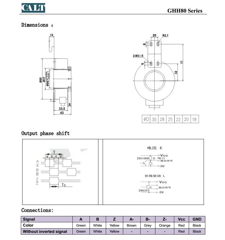
Calt 80mm Hollow Shaft Elevator Encoder 100 360 1000 1024 5000 Ppr Replace Kubler Optical

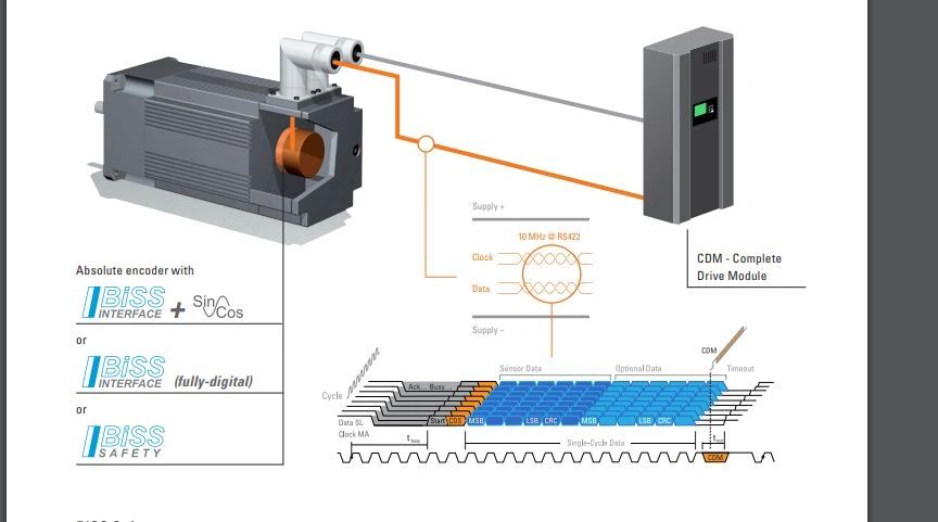
Kuebler -BiSS interface

SICK (USED) Encoder ATM60-P4H13X13 ATM60P4H13X13 1030013 1 030 013 | Encoders:Interface
 Encoder ATM60-P4H13X13 ATM60P4H13X13 1030013 1 030 013 (2).jpg)
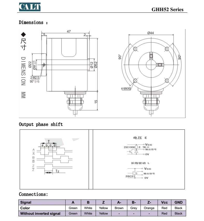
Calt 360 1024 2000 5000 Ppr Hollow Shaft Encoder Replace Kubler Optical Incremental Rotary
