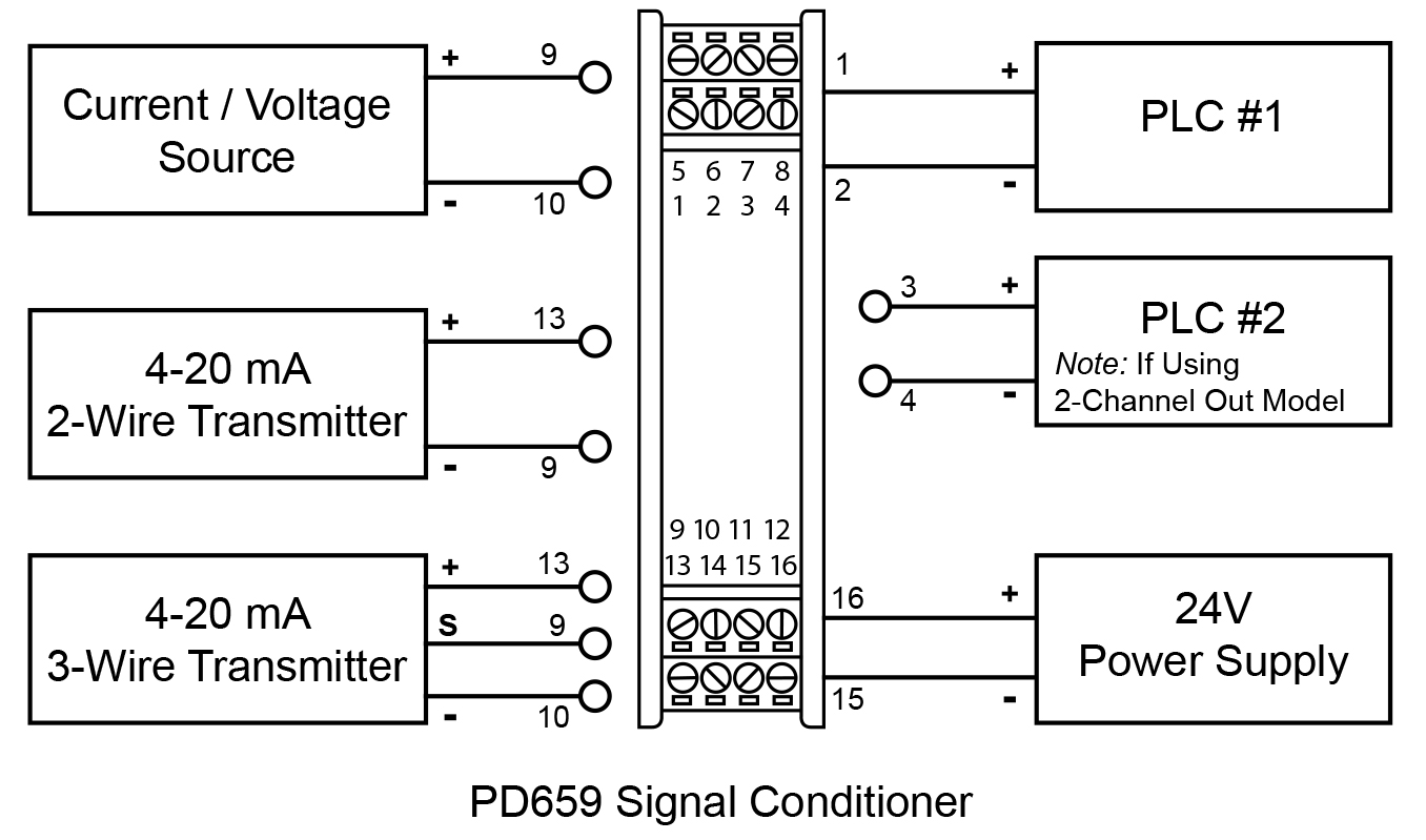
Minco Rtd Wiring Diagram

Honda Xr200 Wiring Diagram, Skygo150 Voltage Regulator for XR200/Actual Wiring/Honda XR200 Modified/Supermoto/DIY Garage PH, 10.03 MB, 07:18, 10,383, D I Y Garage PH, 2021-01-23T08:48:03.000000Z, 19, Iam looking for a 1982 honda xr200 wiring diagram, www.justanswer.com, 904 x 703, jpeg, wiring diagram 1982 honda xr200 xt200 yamaha manual iam motorcycle looking 1981 mechanic bikee wire, 20, honda-xr200-wiring-diagram, Anime Arts
Home » uncategorized » minco rtd wiring diagram. Minco tt176 rtd temperature transmitter tt269 installation and operating instructions manualslib 2 wire programmable tt518 tt521 temptrantm 4 20 ma cur with leads or terminal block connections tt110 tt111 tt150 tt151 tt164 tt231 tt291 tt309 tt700 publication f mod lit 111mnweb doc. Diagram on the right. A1, a2, b1, b2 are the same color, c1 and c2 are the same color).
The rtd connections for the temptran in the wiring diagram below Here are tips how to wire your rtd to a meter by omega engineer, chet. We'll be using 1 platinum series meter, pr11 probe + a d20 meter with an omega calibr. Figure 8 shows rtd wiring. Connect shields to tb4. Secure all wires to the connector boards with nylon cable ties in the holes provided. In this guide tcr is the rtd’s resistance change from 0 to 100°c, divided by the resistance at 0°c, divided by 100°c: For example, a platinum thermometer measuring 100 ω at 0°c and 139. 11 ω at 100°c has tcr 0. 00391 ω/ω/°c: For a copper rtd, 10 ω at 25°c, tcr is:
Rtd Sensor Wire Colors | Colorpaints.co

3 wire rtd color code | Colorpaints.co

3 wire rtd color code | Colorpaints.co

3 wire rtd color code | Colorpaints.co

3 Wire Transmitter Wiring Diagram - Wiring Diagram Networks

3 wire rtd color code | Colorpaints.co

3 Wire Transmitter Wiring Diagram - Wiring Diagram Networks

Wiring Diagram PDF: 100 Ohm Platinum Wiring Diagram
3 Wire Transmitter Wiring Diagram - Wiring Diagram Networks

Temperature Sensor Wiring Lead Color Code - Engine Wiring
